Arduino which is an open source electronics platform has easy to use hardware systems and software packages. Arduino UNO board is one of them. It is the most widely used Arduino board across the globe. It is the favorite one for beginners, hobbyists and students. The major parts of a typical Arduino UNO board is shown below. Since it is an open source platform, there will be some negligible differences in the board when compared to your own board. The major parts are numbered from 1 to 17.
 |
| Image source https://www.tutorialspoint.com/arduino/images/board_description.jpg |
1. POWER USB:-
 After writing the program code in the Arduino IDE, it is needed to transfer into the micro controller. For this purpose a connection between the board and computer is needed. This power usb port (1) is used for that purpose. There will be a USB cable provided which is having a box type end and it is needed to connect to this (1) port. When upload button in the IDE is clicked, the program will be transferred to the board. This port can also be used for giving power. Once the board is connected to the computer, it is sufficient to get power for Arduino board. A power bank can also be connected to the board by using this (1) port.
2. BARREL JACK:-
 Barrel jack is mainly used to give power. By using this (2) port, it is possible to use batteries as power source. It is also possible to power directly from AC power source. Students, beginners and hobbyists often use this port to connect with batteries. In case of a wheeled robot, most of the cases the arduino board and the motors are powered separately. This port helps for increasing the compactness of the system.
3. VOLTAGE REGULATOR:-
 The voltage across the Arduino board will be different. The input voltage will be different to the voltage needed by processor. The voltage needed by the processor may be different to the voltage needed by other components. To avoid these problems, a stabilizer is needed. Voltage regulator (3) will control the voltage given to the board and also stabilize the voltage needed by other components.
4. CRYSTAL OSCILLATOR:-
 Just like computers, Arduino board also want to calculate time. It needs to synchronize the various operations. It needs to perform certain functions at given interval. Without adjusting and calculating time, it is nearly impossible for Arduino to function well. Even simple things will not be possible. Calculating time is the function of crystal oscillator. There will be a number printed on the crystal oscillator. Most probably it will be 16.000. It implies that the frequency is 16000000 Hertz or 16 MHz.
5 & 17. RESET:-
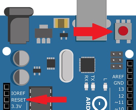 Sometimes, it will be necessary to reset the board. There are two parts in the Arduino program. One is 'setup' and other is 'loop'. Once the program is uploaded to the board, the board reads the code from top to bottom. It reads the 'setup' function only one time while the 'loop' function will be executed again and again. Once it is reset, then the program will start to execute from 'setup' function again. This is what happens when the board is reset. There are two ways to reset the Arduino board. One way is to use an external reset button by using the port (5) or to use the builtin reset button (17).
6. It is a 3.3 v output supply
7. It is a 5 v output supply
8. GND: It means ground pin
9. Vin: This pin can also be used to power externally.
(Most of the components that will be used with Arduino work under 3.3 v or 5.0 v. That is why two ports are dedicated to give as output supply 3.3 v and 5 v. There are totally 3 ground pins denoted as GND. It can be used to give low stage in programming {zero voltage}.)
10. ANALOG PINS:-
There are two signals viz. analog and digital. Analog signals are continuous. There are six analog pins in Arduino UNO, they are denoted as A0, A1, A2, A3, A4 and A5. Mos often these pins are used to connect analog sensors such as temperature sensor, humidity sensor etc. Once the analog signal is received it is converted to digital signal consisting zeros and ones so that the processor can process on it.
11. MICRO CONTROLLER:-
 This is the main part of the Arduino board. It (11) is known as the brain of the Arduino board. It is this part which takes actions as instructed through program. Each board has its own micro controller. Generally the micro controllers are made by ATMEL company. The information about the micro controller is shown on top of it (11). It receives some input, performs some task and gives some output.
12. ICSP PIN:-
ICSP stands for In Circuit Serial Pragramming. It is very uncommon to program ICs before they are soldered onto PCB. Instead, most micro controllers have an in-system programming referred to as ISP header. Some IC manufactures such as ATMEL have a special ISP method for programming their ICs which is referred to as ICSP (In-Circuit Serial Programming).
13. POWER LED INDICATOR:-
This is a way to check the Arduino board. Once the board gets power, this LED should light up. If this (13) light doesn't turn on, then it means there is something wrong in the connection. If the connection is okay, then the problem will be of board. The color of the LED depends upon the board. It may be green, yellow, orange etc.
14. RX & TX LEDs:-
 There are some serial data communication while the board is performing its tasks. At every transmission of such data, TX LED will blink. Similarly, for receiving data, RX LED will blink. This is most often visible when the program is uploaded to the Arduino board. There are also two ports provided namely RX and TX which can also act as digital i/o ports 0 and 1.
15. DIGITAL PORTS:-
These are digital multi purpose ports. They can be utilized as input as well as outputs. If it is defined as input in the program, it will act as input or if it is defined as output in the program, it will act as output. More often, the digital sensors are connected to these ports and define them as input and when the motors are connected, those ports will be defined as output ports. Some ports may be labelled as '~', it indicates that these ports can be used to generate PWM (Pulse With Modulation).
16. AREF:-
AREF stands for the Analog Reference. It can be used to set the upper limit for the analog pins and serves as an external reference voltage to them.